Exploring CNC Routers

CNC routerModern machine tool technology has allowed for many different types of CNC routers to come about. Each piece of equipment has it’s practical use, but knowing which is best for your needs can be difficult.

Below, we go into detail regarding all types of router and accessories. Read along to learn what type of machinery will best fit your machining needs.

Types of CNC Routers

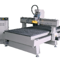
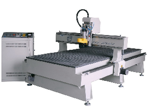
Industrial CNC routers make up approximately 80% of all the CNC routers that are currently in circulation, as many large companies that specialize in woodworking own several of these machines, to meet the deadlines and mass productions of their product (signs, doors and furniture). They are costly, but are built to endure long hours of continuous operation, which justifies the price for businesses.

Mid-range routers are perfect for businesses that produce much less product (such as sign makers and manufacturers of guitars/musical instruments), and also for the enthusiast/hobbyist. This machine is a grade lower than the industrial CNC router, and although they deliver the same quality of precision, the machine is lighter and much smaller than its “big brother”.

Multi Axis CNC Routers are effective when three dimensional cuts are necessary. Four and 5 axis CNC routers provide more variety and flexibility to the operator, and produce a true 3D cut. These types of CNC routers are usually found in artistic industries, and when quick prototyping is needed.

5 axis CNC router
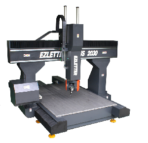
It is not very difficult to operate a 5 axis CNC router. The planned finished product is plugged into a computer (usually forming a 3-D visual model). This completed visual model is then communicated (transferred) to the CNC router, and the carving begins according to the specific instructions that had been programmed into the computer by the operator.

Primarily found in medium to large size factories that focus on wood production, a standard 5 axis CNC router is a very large piece of equipment that costs tens of thousands of dollars (U.S. currency), which virtually makes it impossible for this to be a machine for a hobbyist, who works out of their garage or home-based workshop.

On the positive side, thanks to their large size, 5 axis cnc routers have the ability to carve a material/workpiece that is several feet higher and wider than the machine.

Parts of a Standard CNC Router

Motor (either powered by electric or air). The base plate extends off the motor, and the shaft is found extended from the motor and through the base plate. One end of the shaft, the collet, holds the bit (cutting tool) in place.

CNC Router Table

A computerized numerical control (CNC) router table consists of the combination of a moveable frame, flat work area, and router that is operated via a computer.

CNC routers are used to trim, cut and shape material, such as soft metal, wood and types of plastics, in addition to having the ability to etch three-dimensional designs onto the surface material.

A CNC router table can move back and forth on the X-axis or be stationary. Tables that are categorized as stationary, usually have a gantry (motorized frame) that is mounted under the base that freely moves along the X-axis.

Wood is the most common type of work piece used, but polyurethane and plastic are also common types of material that are found on a CNC router table.
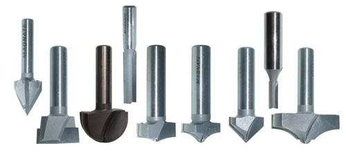
CNC Router Bits

CNC Router Bits

Router bits are classified as profile, helical and fluted, and range in diameter from .2 inches to .5 inches.

Bits rotate at very high speeds (up to 30,000 spins per minute), and depending on the designated cuts, many bit shapes are available (including spiral, round and long bits with a knife type head).

Know Your Press Brake Tonnage

hydraulic press brake
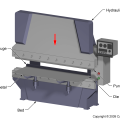
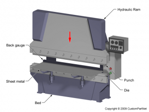
Press brakes are used for bending sheets of metal to a certain angle using tooling known as dies and punches. Although that sounds rather straightforward, choosing the right press brake is not a simple process. To make a wise and informed decision it requires researching series of different factors to determine which press brake options best meet your needs.

Components of a Press Brake

Brake presses usually have an upper and lower section. The upper section holds a piece of tooling such as a punch that normally has a V shape. The lower section holds a matching shape referred to as the die. When the two sections of the press brake are moved together it forces the metal sheet in between to bend.

Background

It is important to identify the nature of the job the press brake will be doing because over 40 different types of forming, cutting and drawing operations can be performed on a press brake.  Some operations must be done alone and other operations can be done in combination.

Failing to consider the characteristics of the press brake can be an expensive mistake.  It is also important to know what tooling will be needed and if special dies will need to be made or sourced.

The type of metal is also critical to know in order to ensure the press brake has capabilities adequate for the job.  General industry press brake ratings are based on mild steel with a tensile strength of approximately 60 ksi (415 MPa).

Metals with higher tensile strengths require proportionately greater tonnage and will have different working characteristics. Some high-strength metals work best when pre-heated prior to bending because they are more brittle than mild steel.

One must also consider the raw material tolerances because there are variations in piece to piece milling metals that can run as much as 50% in hardness and 10% in thickness. Foreign metals often vary even more.  These variations make it important to plan for reserve tonnage in order to prevent overloads of machine stalls.

Tonnage

Press brake tonnage refers to the maximum bending pressure or bending capacity of a press brake.  It is expressed as the force in tons exerted by the press against a workpiece.

The tonnage the press can exert is a function of the torque it develops as well as the strength and size of its parts.  Just as important as tonnage is the energy requirements of the press.

Press Brake Tonnage Chart

(Click to enlarge)

press brake tonnage chart


Click here to access a press brake tonnage calculator

All brake presses should have an energy rating as well as the maximum tonnage rating.  Every job that is completed needs tonnage and that tonnage must be pushed through a specific distance. When one multiplies the tonnage by the distance the result is the energy in inch-tons that is required to do the work

The first factor to consider in purchasing a press brake is the bending force or tonnage required. In order to calculate that number, you can use formulas or refer to manufacturer tonnage charts. The tonnage required depends on the thickness and length of the plates you will use as well as the metal that will be bent.

Bend Length

The second factor to consider is how long the bend will be. You cannot bend anything longer than the maximum capacity of the brake you choose. For example, if the press brake you want to buy has a maximum bend length capacity of 2 feet then you cannot create a bend longer than 2 feet.

It is crucial to verify that the press brake you choose can handle all parts or sheets from the smallest to the biggest required bending lengths.

Back Gauge

Finally, the back gauge is one of the most critical parts of the brake press. It positions the metal part before bending. It is important to make sure that the back gauge can be easily and quickly changed. A lot of time and productivity can be lost when it takes too long to change or readjust the back gauge.

Pneumatic, Hydraulic or Mechanical?

Another consideration is whether the brake press will be pneumatic or hydraulic. Pneumatic presses use air pressure to create tonnage on the ram and they are designed for smaller jobs that do not require a lot of tonnage. Hydraulic presses have two or more synchronized hydraulic cylinders on the C frames that move the upper and the lower tooling.

In a hydraulic press servo-electric brakes utilize a servomotor to drive a ball screw or belt drive to create tonnage on the ram. Hydraulic presses can move up or down at any point in their operation and can even be tilted by putting different tonnages on each cylinder.

This allows more complicated crowning control. These presses are superior for heavy-duty machinery and bigger jobs because they offer greater accuracy, safety and control. Mechanical presses are no longer manufactured due to safety concerns although used mechanical presses are still available on the market.

In a mechanical press an electric motor is used to add energy to a flywheel. When an operator starts the machines a clutch connects the flywheel to a crank mechanism that moves the ram vertically. Mechanical presses are not very accurate nor can the speed of the ram be controlled.

Mechanical presses are not a good choice for high-end fabrication applications.  They can be used successfully in shops that do not need accuracy or control.

The best way to determine the best press brake for your situation is to consult a manufacturer’s tonnage chart. Begin by narrowing down your choice of manufacturer and then begin to study their press brake materials.

It is very helpful to speak directly with the manufacturer to discuss your specific needs because they are very familiar with their press brake products and what applications each machine is best able to handle based on all of the factors discussed in this article and the complexity of a specific client process or application.

Choosing the Right Benchtop CNC Milling Machine

benchtop milling machine
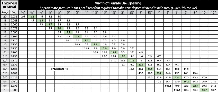
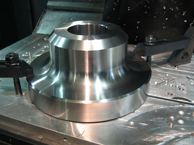
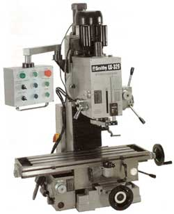
Milling machines have the ability to accomplish many different tasks because the heads can be changed depending on the type of material being cut and the desired shape of the end results. For instance, if the tool bit is not strong enough to cut through a workpiece (steel for example), the machine may be damaged.

On the other hand, if the bit is too strong for softer material (like wood), the workpiece is at risk for damage.

New a Used Milling Machine Basic Parts & Usage

A “cutter” is the most basic tool bit used with a benchtop milling machine, and it is used to cut and shape many different types of material. The cutter is attached to an arbor (also known as a mandrel), which securely holds the cutter firmly in place.

This versatile machine is used in many types of manufacturing shops. A milling machine can be operated manually, mechanically or digitally (via a CNC – computer numeric control panel).

Types of Benchtop Milling Machines

A manual milling machine usually delivers more precision, and is portable and lightweight, which makes it perfect for smaller jobs. Even large companies have a manual version of a milling machine as they are the perfect tool for creating prototypes and completing any light duty work. In addition, manual benchtop milling machinery is usually inexpensive.

Milling machines are usually classified as either vertical or horizontal position (and this simply refers to the orientation of the main spindle).

The recent models of benchtop milling machines are digital, and use CNC technology that requires very little user intervention. CNC milling machine operators still need to be properly trained, to ensure that the machine is operating correctly, and how to input the data and program the computer software.

A benchtop CNC milling machine (also referred to as a “machining center”) is fed specific instructions, via a computer, on how, when and where to cut. This type of machine is more costly and sophisticated than a manually operated milling machine, but CNC milling machines are great for businesses that need to create large volumes of the same type of product.

Bench Top Milling Practical Application

benchtop cnc milling machine in action
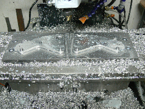
A bench top milling machine resembles a drill press in appearance, but unlike the limitation of a drill press (which you will have to keep the material stable), a bench top milling machine has the ability to move the workpiece toward the cutter.
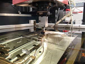
Milling machines are used in a variety of industries including, but not limited to: graphic design, gun making, agricultural design and food

Some items that are milled using bench top or other models of machinery include:

  • After being casted, car engine blocks are then precisely milled by machine.
  • Prior to assembly, a car engine head is also milled.
  • Pistons, values, camshafts and some customized items will also pass through a milling machine.
  • Gears and other intricate machine parts.
  • Scale models.
  • Musical instruments.
  • Firearms.

Benchtop milling machines are used in many different types of operations, in addition to having the ability to drill and bore through many types of material.

There is such a wide variety in the size, cost and ability of milling machines, so it is advised that you determine how the machine will be used and to take into consideration, what is your price range. Used milling machines will offer the lowest prices on initial investment, and many work as efficiently as new versions.

The EDM Process – What Electro Discharge Machining Is All About

electrical discharge machiningSpark Machining or Electro Discharge Machining is used on hard metals, especially the processes that are very difficult for traditional techniques to penetrate. Metal is removed from a workpiece by a rapid succession of constant electrical discharges.

As the material is removed from the original workpiece, a continuous flow of fluid (which is usually de-ionized water or dielectric oil) washes it away. This repetitive process continues, until the final shape is created and completed.

A major (and very important) limitation to this process is that it ONLY works with material that is electrically conductive.

Two main methods of Electro Discharge Machining

They are “ram” and “wire”, and the primary difference is the electrode that is used during the machining process.

A “ram” edm cutting application uses a graphite electrode and a traditional tool. This specially shaped electrode is connected to a power source, and is slowly fed into the original workpiece. This entire process is completed under water, and the fluid serves several purposes including:

  1. Flushing away of cut material.
  2. Serving as a coolant, to prevent overheating and potential damage to the workpiece.
  3. Acting as a conductor between the electrode and the material/workpiece.

When a “wire” edm cutting application is used, a tiny thin wire (usually brass) is used as the electrode.

wire electro discharge machine in actionWire electro discharge machining is an alternative to manual and CNC milling methods, and allows the skilled operator to use the edm supplies, to create intricate designs that would otherwise be impossible.

If you were to observe the wire edm cutting process under a microscope, you will see that the wire doesn’t make contact with the metal piece being cut. The path that the wire follows is controlled via computer, and this allows for complex shapes and designed to be created.

A more simplified way to describe this method is to compare it to: a thin piece of wire being stretched between human hands and used to slice a block a cheese, and continuing to do so, until the desired design is completed.

Although similar in concept, when wire is dragged through cheese, the excess cheese is “displaced”, but when using this edm cutting method, the excess pieces that are being cut away are removed.  In addition, this type of cutting method is used in some of the hardest materials in the industry. This type of edm cutting is used, when a low volume of molds are needed as a prototype.

These methods may take a little longer to complete, than traditional cutting methods, but the results are more precise, and you may not have to purchase as many replacement edm supplies, because this slower edm cutting method allows for the tool to last longer.

The Process Of Machining Titanium Using Modern Machinery

precision titanium machining
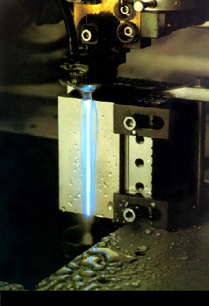
Titanium has become one of the most popular materials used in aerospace applications.  The reason for this are the special properties titanium possesses. Titanium has a relatively low mass for a given strength level and it also is highly resistant to high temperatures.

These properties make it a very good choice for an aerospace material because materials need high temperature resistance and light weight but great strength at the same time.

Titanium is used in the front sections of an aircraft engine and are becoming more and more common in structural and landing gear components.  The one big drawback to using titanium is that the materials is very difficult to machine.

Machining Titanium

Machining titanium is very demanding and requires he right machine tools for the job. It often requires the removal of up to 90% of the weight of the workpiece. When titanium is machined it produces a high-chemical re-activity that causes the chip to weld to the tool which leads to cratering and quick tool failure.

Titanium laso has low thermal conductivity which does not allow the heat generated during machining to dissipate from the tool edge. The inability to dissipate heat causes high tool tip temperatures and excessive tool deformation and wear.

Correct Use of Coolant

Using Coolant in the machining process
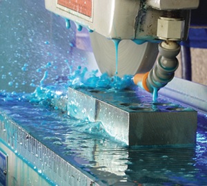
The most important factor to consider when machining titanium or titanium alloys is proper coolant delivery.  The goal is to create a low coefficient of friction.  This results in lower temperatures so the workpiece does not get soft and the tool life is extended rather than shortened.

With pressure and direction, the coolant knocks chips off the cutting edges and provides anti-corrosive benefits for both the machine tool and the workpiece.  Research shows that there is a high correlation between the amount of coolant delivered and the metal removal rate.

Using a high coolant concentration provides lubricity that helps extend tool life, chip evacuation and finer surface finishes. High –pressure coolant through the tool or through an adjacent line parallel to the tool should also be considered to increase tool life and production rates.  Multi-coolant lines should not be used. It is better to use a single line with 100% of the flow capacity to evacuate the chips from the work area.

Synthetic or semi-synthetic coolants should be used at proper volume, pressure and concentrations levels.  10-12% coolant concentration is mandatory.  The flow to the cutting edges should be maximized with a recommendation of 3 gallons per minute or 13 liters per minute at 500 psi for through tool flow.

Machining Tips

  • Rigidity is paramount
  • Coolant, coolant, and more coolant
  • Speeds and feeds have to reduced significantly below what they are for softer metals
  • Cutter material is critical-Use coated carbide cutters
  • Reduce tool stickout-vibrations destroy the surface finish
  • Always utilize gravity to your advantage
  • Horizontal spindles help chips to fall away fro the workpiece
  • Horizontal fixturing requires the use of angle plates or “tombstones”.
  • Keep work closest to the strongest points of fixture
  • Keep work as close as possible to the spindle/quill
  • Know the power curve of the machine
  • Ensure sufficient axis drive motors for power cuts
  • Look for weak links and weak parts of machine structure that could compromise rigidity
  • Check for backlash in the machine’s spindle
  • Identify your drawbar’s pull-back force
  • Watch the adapter for fretting and premature wear-signs of overloading the cutting tool and damaging the spindle and bearings

Non-Traditional Machining

Titanum alloy components often require the use of non-traditional machining methods such as electrochemical machining, chemical milling or laser beam torch.  Chemical and electrochemical methods of metal removal are likely to increase because of their many useful features.

They are particularly good methods for rapid removal of metal from the surface of complex shaped parts, thin sections and large areas and formed parts without damaging the mechanical properties of the metal.

Electrochemical Machining

ECM is the removal of electrically conductive material by anodic dissolution in a rapidly flowing electrolyte which separates the workiece from a shaped electrode. This method can generate very difficult contours and provide undistorted, high-quality surfaces.  When using it to machine titanium alloys the most common electrolyte used is sodium chloride in a concentration of 1 pound per gallon.

Chemical Machining

Chemical machining uses a strong chemical reagent. The part being processed is thoroughly cleaned and covered with a strippable, chemically-resistant mask. Areas where chemical action is desired are stripped off the mask, and then the part is submerged in the chemical reagent to dissolve the exposed material.

Laser Beam Torch Machining

Machining using this process involves removing material from a workpiece by focusing a laser beam and a gas stream on the workpiece. The laser energy  causes localized melting and an oxygen gas stream creates an exothermic reaction forcing the melted material out from the cut.  It is possible to cut titanium alloys at a very rapid rate using a continuous wave CO2 laser with oxygen assistance.

CNC lathes and machining centers can be used to machine titanium and many new models and CNC machining centers are dramatically increasing the milling efficiency of titanium and titanium alloys by including several key elements for efficient titanium machining including active dampening systems, rigid construction, high-torque, high-powered spindles, and high pressure, high-flow coolant systems.

Although titanium and titanium alloys present specific problems for machining, there are several different methods of competing titanium machining. CNC mills and lathes are being specially designed to address this growing segment of the machining market and many advances have already been made making the machining of titanium easier than ever before.

KBC Tools and Machinery Inc. – Their Place In The Machine Tool Industry

KBC Tools and MachineryKBC Tools and Machinery, Inc. was founded by Karel Bass back in 1965 with the original company name being “Kabaco Tools”.  The wholesale distribution company is still headquartered in Sterling Heights, Michigan and their original motto “We Will Not Be Undersold” is still the guiding principle of this discount seller of machine tools to the metalworking industry.

During the decde of the 80’s Karel found new opportunities to help the company grow and bought a supplier’s business located outside of Sand Fransciso. This drove the opening of the first branch of KBC and from there on John Earles VP and Karel Bass figured out how to duplicate the business in other places. When it became clear there would be free trade between Canada and the US in the late 80’s they opened their first Canadian branch.

KBC today remains committed to their original goals of outstanding customer service, top quality tools and competitive pricing.  The company has many long term clients that the staff recognizes by voice when they call. The personalized service and relationships developed with customers’ remains a hallmark of KBC Tools and Machinery Inc.  In 2010 they celebrated 45 years in business.

Where KBC Began

KBC Milling machine

Originally started as a catalog company, KBC is still a catalog driven company. They work with many different manufacturers and carry an extensive range of products including over 100,000 sku’s of MRO supplies.  Their catalog encompasses over 1,000 pages and features name brands customers have trusted for decades including Niagara, Kurt, Titex, Bison, Toolmex, Kennedy, Waterloo, Black & Decker, Makita, PDT, Starrett and Mitutoyo among many others.

KBC works with a broad range of industry market sectors including agriculture, construction, consumer products, culture, environment, fisheries, forestry, Information technology and communications, manufacturing, chemicals, medical and biotechnology, mining, petroleum and gas, service industries, tourism, transportation, wholesale/retail, aerospace, defense, automotive, food & beverage, furniture and wood products, pulp & paper, plastics & rubber, primary and fabricated metal. Electrical equipment and textiles & clothing.

Cutting Machinery

Their range of cutting tools includes bandsaw blades, boring bars, broaches, burrs, carbide drills, carbide endmills, center drills, counterbores, countersinks, high speed endmills, high spped steel drills, hole cutters, milling cutters, reamers, roughing endmills, saws, spade drills, tapping heads, taps and dies, toolbits.

Carbide tooling includes boring bars, carbide inserts, countersinks, cut-off and Grooving, drills, end mills, face mills, threading and toolholders.

Their machine tool lines feature a full range of horizontal and vertical bandsaws, centerless grinders, Cut-off saws, circular saws, cylindrical grinders, drill presses, dust collectors, ironworkers, CNC Lathes, manual lathes, manual lathes with DRO, CNC milling machines, manual milling machines, manual milling machines with DRO, manual and automatic surface grinders, sheet metal machines, and sanders.

Other Equipment They Offer

KBC Horizontal bandsaw
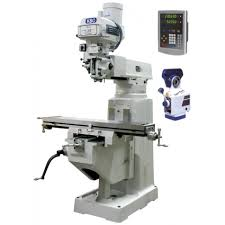
In addition to machine tools they also offer a large selection of abrasives, fluids, measuring and inspection machinery, hand tools, power and air driven tools, tool room accessories and work-holding accessories.

In order to view the pricing of KBC tools and accessories you must shop online and place your products in the cart before you can see the price. This is irritating when you are trying to compare multiple machines for both pricing and features.  If you do not want to place every item you are interested in into the cart to see prices you can download the master catalog as well as their sales flyer direct from the website. This saves a lot of time and hassle.

There is an option to register and create an account on line and take advantage of their tool crib. This feature allows a user to create a list of frequently used tooling so that one need not search for the same tools every time you visit the website. It also provides for faster checkout and notification of special sales promotions including limited quantity closeouts, overstock blowouts, special buys and more.

ISO Certification

Quality is a key principle for KBC Tools and Machinery, Inc. They hold a 9001 ISO certification and they provide their customers with a 100% satisfaction guarantee. In 2010 they unveiled a new 100% satisfaction guaranteed logo. If a customer is not 100% satisfied with their purchase for any reason the customer can return the unused item or items within 30 days along with the receipt to receive a replacement, exchange, full credit or refund.  This is an unusually generous guarantee for a machine tool supplier but it has been their policy since the company started.

KBC president Paula Bass had the following to say about the new promotional effort stressing their quality guarantee: “We’ve always stood behind our products and we’ve aimed to delight our clients every time out. 100% KBC satisfaction guaranteed is our way of reminding customers that we are not satisfied until they’re satisfied.”  When a customer returns an item KBC ensures a quick and painless process. Normally a customer can expect a full credit or refund within 24 hours of KBC receiving the returned item.

KBC can offer this guarantee because they are in a unique position to support it with a product return system that runs extremely smoothly.  When a product is returned KBC inspects it and examines the same product on the shelves at all branches to ensure it meets the company’s strict and demanding quality standards. This can be done because KBC has very few returns. It actually boasts one of the lowest return rates in the industry.

Another important feature of the KBC website are the links to manufacturer websites where you can view details of the manufacturer, their company and their products apart from KBC information.  They provide links to all of their suppliers.

KBC Tools and Machinery, Inc. has three US branches in Los Angeles, Chicago, and Detroit and well as a machinery division in Sterling Heights, Michigan.

Cincinnati Press Brakes – Industry Leaders

Autoform press brake
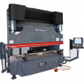
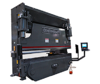
As one of the industry leaders in press brake manufacturing, Cincinnati has been creating high quality machine tools for well over 100 years.

With a variety of different choices, Cincinnati press brakes, sometime referred to as a Cincinnati brake press, are available in various options depending on your specific machine needs and its exact requirements. Whether using the Maxform series, Autoform + Series, Proform + series, large press brakes or a Baseform series press brake, each choice is more effective and efficient than all of the competition. Not stopping there, Cincinnati is one of the most trusted and respected brands in the industry.  Each individual model is manufactured to fit virtually any type of machine tool in order to provide exact precision and to meet exact job specifications.

Autoform + Series

Featuring a three sigma RAM repeatability, the Autoform series press brake is one of the most advanced of its kind.  Showcasing a touchscreen machine interface with offline control capabilities through Bend Simulation Software, there aren’t many choices in the industry that are better than this one.

Also using thickness compensation controls and optional back gauges that allow up to six axes, Cincinnati has definitely made one of the best press brakes available with the Autoform series.

Maxform Series

maxform press brake
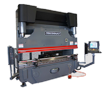
Providing capabilities that are similar to the Autoform + Series, the Maxform series press brake offers amazing RAM and back gauge speeds. Not only that, this specific type of press brake incorporates Bolt-on RAM noses for specific tooling and exact five-axis back gauge abilities.  Adding to their unique specifications, the Maxform series is ANSI B11.3 complaint.

Baseform Series

There’s no question that one of the main reasons that Cincinnati is head and shoulders above the competition is because of their diversified product line that is not even comparable to most homemade press brakes. Continuing to impress their customers for the past 100 years, the Baseform series is ideal for all heavy duty construction equipment. Still offering some of the same features as both the Maxform series and Autoform + series, this specific style incorporates a world class offline bend operation simulator and a touchscreen machine interface while continuing to be complaint with ANSI B11.3 guidelines.

Proform + Series

proform press brake
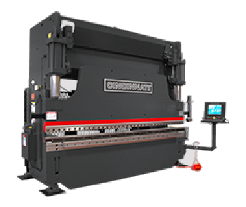
With a three-sigma RAM repeat level, the Proform press brake series is ideal for a variety of different machining needs.  Also including a graphical tool library with unique part views, this series of press comes with a five year parts warranty. In addition, like the other Cincinnati products, the Proform models are completely ANSI B11.3 compliant and are made to fit different back gauges of up to five axes.

Benefits of 5 Axis and Precision & Laser Machining

laser machining
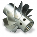
Before laser machining, traditional machining tools included mills, planers and lathes.  Although quality results have been achieved with traditional methods, LBM (laser beam machining) creates greater accuracy in less time.

Laser cutting technology uses a laser beam to cut very precise patterns into all sorts of material (including paper, wood, metal and plastic), leaving you with a high quality finished product with refined edges.

A computer directs the high-powered laser beam, and the material is vaporized, burnt or melted.

Laser machining is commonly found in large industrial plants, but current times are finding this type of technology in schools, small businesses and the home of an enthusiastic hobbyist.

Some advantages of laser cutting:

  1. Precision machining when thin aluminum and steel is being cut.
  2. Energy efficient.
  3. A laser beam will not wear down during the process.
  4. Cutting is faster than traditional methods.
  5. Contamination of a workpiece is reduced.
  6. Complex shapes and intricate details can be created with lasers.

Before laser machining, the machine and the work-piece needed to be measured (and calibrated) at least twice. Now, precision machining is possible thanks to this new technology, because the machine is set once with the specifics, and the cutting process is done automatically.

Other Benefits of Multi-Axis Machining Include:

  1. 5 axis machining
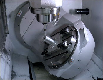
Laser control with 5-axis machining and 6-axis machining.
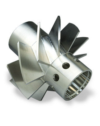
  2. Minimal (if any) distortion to the workpiece.
  3. No lubricant is needed during the cutting process.
  4. No manual force applied to workpiece is necessary.
  5. Ability to cut complex shapes.
  6. Easier and quicker than traditional cutting methods.
  7. Contamination to the work-piece is minimal, if at all.

Damaging material is minimal, because laser machining is a much gentler process than the machines used in the past. The versatility is incomparable to traditional cutting, as laser machining can drill, mark and scribe into ceramics and thin metals, as well as process plastic, silicon, diamond and graphite, within one micron.

Negative Aspects of Laser Machining

The negative side of laser machining is minimal, but it is information that needs to be shared.

A laser cutting machine needs to be placed in a well-ventilated area, as some plastics (when melted) may produce toxic fumes.

A few types of material cannot be cut via a laser machine. Copper is usually too thick to be cut with a laser, and more importantly this material reflects too much light. Crystal, glass and other brittle material cannot be properly cut with this type of technology.

Laser beam machining, as stated above, is a quicker process when compared to traditional methods, but consistency may vary, due to the thickness and type of material being cut.

Types of laser machining processes available

precision machined partCutting: a laser beam passes over a specific type of material and vaporizes away material, to create a certain type of cut or complex shape.

Drilling: The advantage is that laser drilling allows you to drill into hard to reach places.

Heat Treat: This heat/cold controlled process is useful in industries that need to change the microstructure of metal material.

Scoring: is the process that designs a crease in the material, to allow bending or separating of material to be easier.

Scribing: is when specific types of characters or symbols need to be carved into the material. Laser machining allows this process to be effective and simple.

How Material Handling Has Evolved Over the Years Thanks to Modern Machines

Material Handling Equipment

The roots of modern material handling devices are found far back in man’s evolutionary history.

Way back in primitive times it did not take long for humans to recognize that it was easier to move a heavy object if a round object could be placed underneath it like a log. The logs allowed the object to be rolled over them.

With this primitive knowledge the “Sledge” was invented which is a blending of a wedge and a sled. They cut grooves into the rollers so it needed less energy to create a turning motion. Eventually this became the axle. They learned how to use wooden pegs to secure the sledge so that when it rested on top of the roller it did not move. This eventually led to the cart.

Over time, as people became more environmentally aware and needed more durable carts and moving devices, a switch occurred from wood to metals. Throughout history there has always been a need for vertical transportation devices to move heavy loads in factories and at docks.

Early on, lifts relied on man, animal and water power developed by agricultural societies to lift heavy loads up until the Industrial revolution. In the 18th century, machine power began to be developed and applied to lift technology.

In the mid 1800’s we see the first mechanical lifts. In England they installed the first elevator driven by belts. About ten years later, in 1846, the first hydraulic industrial lift made its appearance.

It was powered by water pressure. Electric driven lifts date back to 1889. This changed industrial material handling by enabling faster movement of materials. Other powered lifting and moving devices quickly followed as the engineering of machines made swift advances.

Today, industrial facilities and manufacturing operations all utilize material handling and lifting equipment. Most of today’s lifting equipment is powered with hydraulic power used in combination with leverage.

Common Material Handling Equipment

cranes and hoists

Some lifting equipment uses electromagnetic power and others mechanical or electric power to move or lift objects.

Employing leverage reduces the amount of force required to lift very heavy objects.

Commonly used material handling equipment in today’s manufacturing and industrial applications include banding machines, forklifts, die handling , hoists, cranes, conveyor belts, lifting frames, carts, pallet jacks, skid lifts, vibratory feeders and work platforms and lifts.

How Material Handling Works Today

Nowadays, material handling and the transportation of parts is easily accomplished using a vibratory feeder or conveyor belt. Both machines can move large and small parts from one area to another. Most of the time, these machines are used within a production line so that materials move efficiently from one process to another.

Banding machinery is most often used as part of a packaging process. These machines use a variety of different materials including plastic bands, metal bands, shrink wrap, bags and vacuum bags.  Not only do these machines work to package products for shipping, they are also used to hold parts and materials together on pallets for storage and transportation.

Forklifts play a crucial role in fetching and moving large objects, pallets and more within the plant and throughout the plant yards or on a dock for example. In areas that are too small to accommodate a forklift, pallet jacks or skid lifts are commonly employed to help move heavy pallets.

There is no question that businesses today need and benefit from a variety of materials handling machines. Not only do they save time, they also contribute to safer working environments, reduce physical strain and increase efficiency & productivity.

Metal Bending Machines, Brakes & Manual Benders

metal bending
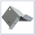
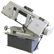
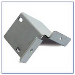
A bending machine is the piece of equipment that is used to bend a flat piece of metal into a specific irregular shapes. CNC bending machines are one of the most recent technologies that deliver cost effective precision to metal shaping.

Universal metal bending machines easily adjust to accommodate a variety of shapes, and can be upgraded and customized at the users need.

A bending brake is a machine used by metal workers, to easily and effectively bend metal into a variety of shapes. A cornice bending brake machine is great for creating creases and simple bends.

A box and plan bending brake machine allows for more versatility, as it goes beyond simple bends, and the user can create box and pan shapes by removing and/or rearranging the blocks. Once it is formed (bent), then the box shape is then seared by welding, soldering, screwing or riveting them together.

Usually metal bender machines fall into four different bending categories, and they are (a) Rotary-draw (b) Compression (c) Roll and (d) Stretch. Each type, of course, has limitations and advantages.

Rotary-draw metal benders are commonly used to bend pipes and tubes.

Compression metal bending machines are used when material needs to be bent more than double the radius of the tube.

Metal bender tools/attachments

rotary draw bending

  1. Standard tool attachments are classified by the type of bend generated. All bends that do not have an extraordinary geometric design are considered to be a “standard” bend.
  2. Offset bending tools are used when 2 bends are required (with a gap between the pieces). This is created in one step with this metal bending attachment.
  3. U-Bending (narrow bends) is achieved with a bending mandrel.
  4. Edge bending tools are needed to create highly accurate angular measurements.
  5. Torsion metal bending tools are used when the workpiece needs to rotate on its longitudinal axis.

Metal bending techniques

Air bending is considered to be a very common type of metal bending technique.  Basically, the metal piece comes in contact with the punch tip and outer edges of the die. The punch is then forced in the “V” shaped opening and the shape is created.

air bending process
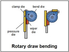
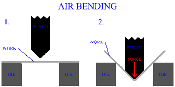
Bottom bending is the metal bending technique that is used when the angle of the finished piece should identically match the die angle.

The three roll push (also known as “TRPB”) is basically a free form way to bend geometric shapes that consist of several simple curves. During this process, the metal pieces are guided between the supporting and the bending rolls, and pushed toward the tool.

The roll metal bending technique is used to form coils when a piece of metal is passed through three rollers, which apply pressure that causes this type of bend.

Heat induced metal bending techniques requires temperatures starting at 800 degrees, and can exceed 2,000 degrees Fahrenheit. Once the coil has reached the desired temperature, it is placed against the metal to form a shape. After the bend/shape is achieved, then the metal is cooled via a water or air spray.

Final Word

When considering a metal bender purchase, it is advised to analyze your needs, and what exactly your final results should be. Other considerations should include the type, size and shape of material you plan to bend. Also, the daily quantity output is also going to play a significant role in your final purchasing decision.

Check out our variety of Metal Bending Machines, Brakes & Manual Benders for sale Here