Comparing Vertical Millers To Horizontal Millers

Vertical MillerThe first vertical milling machine was developed in the 1930’s as the Bridgeport style vertical miller. This Bridgeport style miller is also known as a knee miller or turret mill. Horizontal millers were created much earlier; first introduced around 1818. The new vertical design placed more importance on versatility and economy over higher speed metal removal rates offered by horizontal milling machines.

This versatility has made vertical millers the most prevalent design of milling machine in existence today. Horizontal millers are typically reserved for milling operations where duplicate parts are being created and when high metal removal rates are required.

Advantages Of The Vertical Miller

Vertical type millers offer many advantages over the older horizontal style milling machines. First, it’s important to understand the features that distinguish a vertical miller from the rest.

Key features of vertical millers include:

  • Sliding arm or rams, which allow movement of the work piece toward and away from the vertical column.
  • Knee and column support for the machine work table, which enables vertical movement of the workpiece in relation to the milling tool.
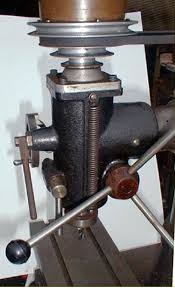
  • The spindle, motor and drive pulleys are held by a one piece tool head.
  • Saddle designed to support the work table and to enable movement of the workpiece toward and away from the vertical column.
  • Some milling machines offer the ability for the tool head to be tilted front to back or side to side.

An important advantage of the mechanical vertical miller is the retractable quill, which moves in and away from the cutting tool without need for cranking the work table up and down. This increases productivity and milling efficiency by reducing operator fatigue. Movement of the work table is still possible for making adjustments, however.

The next advantage is the vertical machine’s ability to easily make angle cuts. Horizontal milling machinery must either have the spindle made at an angle or the work piece must be positioned at the appropriate angle. Vertical millers have an adjustable table that can simply be tilted by the operator to cut at any angle.

Vertical millers are much simpler in design than horizontal machines. The one piece cutting tool eliminates the need for additional gearing inside the vertical column.

Advantage Of Horizontal Millers

The main advantage of the horizontal type miller is that they are much more rigid and can use cutting tools which remove more metal in less time. Vertical machines must use smaller tools which can accomplish the same results, but at a slower rate of speed. These smaller tools do, however offer more precise cuts, which is advantageous for production of small or intricate parts.

A horizontal miller can quickly and efficiently create duplicate parts and parts that require the removal of a lot of material. In this way, horizontal milling machines are more cost effective to use than milling with vertical machine tools. For this reason, horizontal millers are commonly used to mill large automotive components.

Newer milling machines are integrated with CNC or computer numerical controls making both styles of millers much more efficient and precise. The main differences are still the same, which is why vertical milling machines are used for their versatility and precise milling applications.  Horizontal millers are commonly used for milling of large parts and duplicate part milling applications.

3 Common Industrial Grinders and Grinding Machines

Industrial Grinders and Grinding Machines

Grinding and grinders machines have been used in industrial facilities since the early 1900’s. They are among the most commonly used machine tools in manufacturing and fabrication facilities today.

Disk Grinders

Disc grinders, sometime referred to as angle grinders or side grinders, can be handheld as well as machine-mounted machine tools. They consist of one or more circular spinning abrasive wheels or disks that are designed to remove material from a work piece. The grinding or polishing of parts is complete having pressed the material against the broad side of the continuously spinning abrasive wheel.

The machine mounted disk grinder is similar to a disk sander in which a circular spinning wheel in mounted vertically, perpendicular to the work – table. The only difference is that an abrasive grinding wheel is used instead of sand paper. The abrasive grinding wheel is effective for metal removal applications, whereas sand paper is only useful for wood or other softer materials.

The handheld disk grinder can be used for metal grinding, polishing and cutting applications. Since the machine tool is handheld, the process is less precise and more prone to error. For this reason, the handheld version is used mainly for grinding, cutting or polishing of very large structures or parts that cannot be placed on a work table.

Bench Grinders

Bench grinders are rinding machines commonly found in maintenance and fabrication shops. They are a very simple design of machine consisting of dual abrasive wheels with the narrow side exposed. The grinding and polishing of parts is accomplished by pressing the part against the narrow side of the grinding wheel.

Typically, two different grits of grinding wheel are equipped; one courser wheel meant for removal of material, and the other a finer grit wheel meant for finishing or polishing of parts. This grinder can fairly accurately grind angles thanks to an adjustable guide. The guide consists of a half inch, flat steel plate attached to the machine in front of the grinding wheel.

The wheels can easily be removed and replaced with the desired grinding wheel.

Tool & Cutter Grinders

Tool and cutter grinders are used to sharpen machining tools, bits and many other cutting tools. These are among the most versatile of all grinding machines and are capable of grinding functions such as: surface grinding, cylindrical grinding and complex angle grinding.

There are two main types of tool and cutter grinders; mechanical and CNC grinding machines.

Mechanical Tool & Cutter Grinders

The mechanical version requires a high level of operator skill since all adjustments must be made manually. In fact, the entire grinding and cutting process is very complex because the table and tools can be adjusted laterally and longitudinally. The operator must know how to tilt the grinding head to adjust to the many different angles.

For this very reason, computer controlled cutting and grinding machines are becoming more popular.

CNC Tool & Cutter Grinders

The CNC grinding machine requires less skill than the mechanical version since the machine operates precisely according to the user specifications. These grinding machines operate on up to 5 axes and also operate similar to a machining center. Measurements and adjustments to the grinding and cutting heads are made using sensors or lasers, making all operations very accurate.

New Twin Turret CNC Lathe From Germany

Spinner TTC 300 SMMCY CNC Lathe Specs

Quickly replacing mechanical production turning machines are CNC lathes. Most notably for turned part production due to their ease of use, efficiency and fine accuracy. German engineering has gone a step further by creating a computer controlled lathe with dual turrets and spindles.

German based company, Whitehouse Machine Tools, recently released a multi axis CNC Lathe with twin opposed spindles. The Spinner TTC 300 SMMCY twin opposed-spindle, twin-turret CNC lathe offers a number of new features which can increase product quality and production speed.

The CNC lathe is available in two models. The first is designed to process 42mm bar stock and the second can process 52mm bar stock.

  • Each turret is equipped with its own tool stations
  • Each tool station can hold 12 cutting tools
  • Uses 6,000 RPM tooling
  • Main spindle rating: Larger model – 6,000rpm / 12KW Smaller model – 5,000rpm / 19KW
  • Sub Spindle rating: 7,000rpm / 8KW for both models
  • Top turret has a Y-axis  of ± 40 mm
  • Cast iron bed
  • Top turret can adjust to 16 tooling positions
  • Maximum turning length: 400mm
  • Maximum turning diameter: 250mm
  • Machine Weight: 3.5 Tons
  • Dual Direct Drive Spindles with built in motors
  • Large preloaded ball screws offer efficient vibration absorption
  • Liquid cooling system built into each turret
  • Turret indexing time: 0.15 seconds
  • CNC System: SIEMENS 840D-SL or FANUC 31i. Both with a 15” LCD screen.

The size and configuration of these machine tools are becoming increasingly popular for milling complex turned parts with tight tolerances.

Advantage Of A Dual Opposed Spindle Lathe

Each spindle has its own built in motor which directly drives it and built in cooling systems which provide compact and efficient cooling of tools and material. The absence of a drive belt or gear chain offer lower vibration during operation, allowing this CNC turning center to produce turned parts with improved machining quality and accuracy.

The dual spindles are positioned opposite one another and the main spindle is positioned higher than the secondary spindle. Both spindles work together to simultaneously machine each part quickly and accurately.

The computer controlled direct drive feature offers increased acceleration and deceleration of each spindle. The result is increased productivity due to minimized part turning down time and a high quality finished product.

The turning machine is capable of making heavy cuts and hard part turning without sacrificing quality or damaging cutting tools. This feature increases productivity even further.

Spinner TTC 300 SMMCY CNC Turning Center Accessories

Optional features for the CNC lathe include a robotic loading and unloading system and a chuck part storage area.

All CNC lathes are designed to produce turned parts quickly, accurately and automatically; most accomplish this with a single turret. The added features of this twin turret, dual spindle turning center allow a single machine to turn parts almost twice as efficiently as single turret CNC lathe machines.

Boring Mills: Horizontal Or Vertical, Which Is Better?

Horizontal Boring Mills vs. Vertical Boring Mills

Both vertical and horizontal boring mills are capable of performing a variety of drilling or boring operations both manually and automatically. The tool head and workpiece typically move along 3 axes known as the X-axis, Y-axis and Z-axis.

The X-axis is the cross travel, the Y-axis is the vertical travel, and the Z-axis is the main axis which drives the work piece toward the spindle. Additional axes include the C-axis, which is the work spindle itself and the B-axis, which is the centerline of the rotary worktable, if equipped.

The main difference between a vertical boring mill and a horizontal boring mill is the machine setup, workpiece setup and the machine’s tooling configuration.

Vertical Boring Mill

Vertical boring mills are also called vertical turret lathes. They operate very similar to an engine lathe if it were turned up on end, and can perform almost all common lathe operations. The machine can perform operations including turning, boring, facing, tapering, and cutting of external and internal threads.

Parts are formed in a vertical boring mill by the workpiece being rotated around its Y- axis while the boring head moves linearly, very similar to that of a vertical lathe.

Characteristics unique to a vertical boring mill include:

  • The workpiece is held by a horizontal table that rotates around a vertical axis
  • Non-rotating tools can be fed either horizontally or vertically with the use of the cross rail mounted turret slide
  • A side head which can be fed both horizontally or vertically

Vertical boring mill applications include machining: water turbine runners, turbine casings, ring gear blanks, large pipe flanges, locomotive tires, and machine tool tables.

Horizontal Boring Mill

Horizontal boring mills are capable of performing many different machining functions including facing, boring, shaping, tapping, reaming, drilling, contouring and milling.

They are used primarily for boring out large parts with the use of a horizontal spindle. This means that the machine’s spindle is parallel to both the ground and the work table.

One advantage of this style of machine tool is that very large parts can be placed on the machine’s worktable using an overhead crane. Parts larger than the table can still be milled, even if the part hangs off the sides of the table. The only requirement is that the part is stable on the worktable to prevent potential operator injury or machine damage.

The setup of horizontal boring millwork and tools are similar to those found in lathe and standard milling machines. Parts are fabricated by the work-piece being placed on a worktable while the boring head rotates around the X-axis, similar to a horizontal milling machine. In fact, horizontal boring mills have often been confused with horizontal turret lathes and the terms have been used interchangeably.

Boring Mill Types

The first boring mills were designed to create a rough cut of the part, which required a second machine tool to finish the part. Newer machine tools, known as precision boring mills, are capable of creating very detailed, finished parts.

The table type of boring mill, also known as the universal boring mill, is the most common as well as the most versatile.

Boring mills can be mechanically operated, but most modern machines use computer numerical controls (CNC), which deliver very precise and accurate machined parts.

Industrial Furnaces and Ovens: Finding The Right Foundry Machine Tool For The Job

The Right Foundry Machine Tool For The Job

Commonly found in industrial facilities, you’ll find furnaces and ovens perform a variety of functions. These functions include melting metals, heating of metal to alter its hardness, and curing of metal parts. These machine tools are commonly used in foundries, but some can be used in other areas such as the main production floor or in a lab.

The key is to find the right heating and melting machine tools for the job. This furnace and oven guide was created just for that purpose.

Metals such as iron, silver, gold, copper, steel, aluminum and brass can be processed using the following furnaces and ovens:

Furnaces – Induction Heating and Melting

Induction furnaces are electric furnaces in which metal is heated by large amounts of electricity being inducted into it. The process consists of a high frequency alternating current being passed through a strong electromagnet into the electric conducting material. Furnace frequencies range from 50 Hz to 400 kHz or higher depending on the capacity of material being melted and the speed at which it can be melted.

The metal is heated from the inside by the creation of Eddy currents, also known as Foucault currents. This causes the metal to melt once the currents have heated the metal past its melting point. Overheating of the furnace itself it prevented by water cooled tubing which is wrapped around the outside of a layer of refractory, tightly packed around the graphite crucible.

The biggest advantage of using an induction furnace is that they are the cleanest, most energy efficient and easily controlled of all melting furnaces.

Induction ovens work similarly, but have a less powerful electromagnet and lower frequency of electricity. These ovens can be used for altering the hardness of metal parts or raw material.

Typically, an oven would be used to make metal softer in preparation of the next production process such as milling or extruding. A finished metal part can also be cured or hardened to its final hardness in an induction oven.

Smaller induction ovens can be used in labs to heat up liquids or test metal purity. Some are even small enough to be placed on a countertop and function by the electricity being transferred into a metal plate. A beaker, pan, etc. can then be placed on the plate to heat its contents.

Annealing Furnaces

Annealing furnaces are also known as heat treat furnaces and use gas or electricity to create internal heat. They are long, enclosed machines with an internal belt used to carry material and parts through the furnace.

Annealing furnaces consist of a series of chambers, which can each be adjusted to heat and/or cool the material in such a way as to change its properties in specific ways. Heat treatments are most commonly used to harden or soften materials in preparation of further production operations.

These furnaces are capable of completing heat treatments in a matter of minutes rather than hours thanks to use of Rapid Thermal Processing (RTP) or Rapid Thermal Annealing (RTA). This makes this particular type of furnace perfect for a facility in which parts or material continuously need to be softened or hardened on a regular basis.

Vacuum Furnaces and Ovens

Vacuum furnaces are used to heat metals to extremely high temperatures in an atmosphere free from outside gases. This type of furnace can be used for heat treatment, sintering and brazing applications.

Some benefits of using a vacuum furnace include: uniform heating from 2000 – 2800 degrees F, minimal chance of contamination from foreign gasses such as carbon, decreased chance of material oxidation and faster cooling of heated materials.

History Of The Automatic Screw Machine

The Evolution of Automatic Screw Machines

Fully automatic, high-speed lathes are commonly known as automatic screw machines. It could even be considered a highly developed type of turret lathe due to the fact that the cutting tools are carried in a turret of some form. They operate on a vertical or horizontal axis, depending on the machine tool style.

The machine tool itself is automatic in that it uses the cutting tools to automatically cut into the turning stock to form any quantity of duplicate parts. The machine operates mechanically, but the operator can set the machine up to form parts either by using mechanical controls or CNC controls depending on the style of machine. CNC stands for computer numerical controls

Automatic Screw Machine History

The first automatic screw machine was patented in 1865 by Brown & Sharpe and then by Christopher Spencer in 1873. The idea was taken from the turret lathe and was created as a way to produce small turned parts more efficiently.

The idea was to create a turning machine that could make the exact same turned part automatically and repetitively. It was called the screw machine because its intended use was to create screws and pins.

The first automatic screw machine had a single spindle; multiple spindle models were introduced in the later 1800’s. The multi-spindle machines were not widely used until the coming of World War I, since manufacturing efficiency became extremely important.

The design feature, predominate to the use of the turret, and making the automatic screw machine truly automatic is the use of drum cams. Drum cams are fixed upon a series of removable cam components. These are compatible with the size of the workpiece and parts to be formed. The cams allow the automatic movements of the different operative machining tools to be performed. It is the action of these cams that give this machine tool its automatic classification.

This particular machine tool was initially designed to make screws, pins, and other small parts from bar stock, which was passed through the hollow spindle from the rear of the machine. When the chuck opened up large enough for the bar stock to be fed through it was pushed forward until it hit a stop located in one of the turret’s tool holes.

The bar feeding device was operated automatically by weight, and was called a wire feed because screws were once made from portions of straightened wire. This same machine tool is now capable of feeding rather large bars of stock, much larger than thought possible in the early years of machine development.

The Modern Automatic Screw Machine

Many modern automatic screw machines are equipped with multiple spindles and are capable of operations such as index drilling, screw slotting, threading, counter boring and more. They are also capable of operating by more than purely mechanical means; modern machines utilize hydraulic, electric, or CNC. Again, CNC stands for computer numerical controls.

Additional Automatic Screw Machine capabilities include:

  • Automatic loading of the workpiece
  • Automatic  starting of the machine and coolant
  • Automatic changing of the tools, speeds and feed rate
  • Automatic inspection and measurement of the part
  • Automatic  unloading of the finished part
  • Automatic operation restart

Some screw machines can be equipped with a hopper or magazine in which metal parts can be fed. When they pass into the chuck, they will be gripped and machined according to operator specifications. This machine tool process is completely automated, meaning that the only thing required of the operator is to ensure that the hopper stays full and that tools stay sharp.

Hydraulic Press Brake With Automatic Tool Changer & 220 Ton Capacity

The Latest Hydraulic Press Brake

A new 220 ton hydraulic press brake equipped with an automatic tool changer, known as the ToolCell 220/40, was recently introduced by the LVD Strippit firm. Previous ToolCell press brakes manufactured by the company up until now have offered superior metal bending operations, but have been limited only by capacity. Older models had as little as an 80 ton capacity; the newest ToolCell 220/40 model was manufactured with a much larger capacity of 220 tons and offers 160” bending length. ToolCell 220/40 The 220 Ton press brake is designed for small to medium batch production. Set up time is reduced and metal bending efficiency is maximized with its equipped automatic tool changer and tooling storage system.

Strippit ToolCell 220/40 Press Brake Features

Features of the Strippit 220 Ton press brake include:

  • Tools are automatically and precisely placed with the ToolCell 220/40 automatic tool changing technology; eliminating the need for manual adjustments of tooling.
  • Automatic unloading of previously used tool setup and loading of tool setup for the next process.
  • Tooling capacity of two rows of punches on top and five rows of Vee dies on bottom.
  • 220 Ton maximum bending capacity.
  • 160 inch bending length capacity.
  • Rigid frame with hydraulic and electronic real time angle control to ensure accuracy.
  • LVD’s patented Easy-Form® Laser ensures accuracy and consistency of every part with its auto correction and angle measuring technology.
  • 19-inch touch screen control panel known as the Touch-B.
  • CADMAN-OEE PC-based Windows® compatible process management software.

The Touch-B control panel can control all parameters of the machine via graphic icons. This machine tool can also be programmed offline using the CADMAN®-B Tool Changer module. Configurable machine options include adjustable stroke, open height front supports and sheet following units. The machine can handle metal bending and folding operations with more than six different tool setups per day and handle parts with multiple complex bending points. It also offers extremely accurate tool set placement; tools are always easy to find thanks to the tooling storage and holders. ToolCell press brakes offer everything a sheet metal industrial operation needs to efficiently produce sheet or plate metal parts. The machine operator can be preparing work pieces for the next job to be completed while the machine is automatically setting up the next tooling setup.

About The Company Behind The Press Brake

The LVD Group was founded in 1925 by George Wales. Wales developed a simple spring that proved to overcome stripping difficulties for material blanking operations. They were the first in the punching industry to develop fully guided self-stripping, self-contained tools. Since then, they have expanded to first manufacture a range of different metal fabrication products, then hydraulic press brakes in 1954. Next, they expanded to punch presses and load/ unload systems; they began introducing CNC machinery in the late 70’s. They are now a leading sheet metal machine tools manufacturer based in the U.S.A. and offer their machine tools worldwide. Their offered machinery includes machine tools like turret punches, guillotine shears, laser cutting machines, press brakes and automation systems.

Machine Tools To Be Featured In ABB Robotics Technology Days On May 15th

Automated Machine Tools
ABB Robotics Technology Days On May 15th

ABB Robotics Technology Days

Modern machine tools are going to be a featured topic during the Technology Days event hosted by ABB Robotics, a leader in automated machine tools. The event is to be held on May 15th, 2013 at their U.S. headquarters in Auburn Hills, Michigan and will feature robotics equipment for virtually all industrial applications.

The event will have industry experts available as well as a variety of training seminars that all guests can attend. The main attraction will be the numerous machine demonstrations and machine tool automation exhibits. The overall theme of the event will be the upgrading or expanding of existing robotic automation in machine tools.

Machine Tool Exhibits & Events

Robotic machine tool exhibits are to include:

  • Automotive powertrain equipment

Escorted tours and live demonstrations of robotic powertrain machine tools in action are among the highlights of this automotive industry exhibit.

  • Automated painting machinery

Painting machinery ranging from basic to complex machine tools will be presented here. Demonstrations of painting applications will be featured, as parts of all sizes will be thoroughly coverd.

  • Packaging lines, including automated picking machines

These booths will feature automated packaging and order picking machine tools that use new software developed by ABB Robotics – which offers much easier machine programming. Demonstrations of the high speed FlexPicker will also be one of the main highlights of this exhibit.

  • Welders and laser cutting machine tools

These exhibits are to include robotic welding and cutting machines: Single welding stations, Complex welding stations and cutting systems.

  • Palletizing and de-palletizing machinery

This booth will include automated material and part palletizing machinery commonly used in the packaging process.

  • Service and training

These booths are dedicated to training and remote demonstrations of a variety of new and existing machine tools with added robotic components.

  • Machine tool safety and general application

This exhibit will focus on integrating new machine technologies in industrial facilities and proper safety precaution when integrating and operating robotic machine tools.

  • Parts assembly machinery

These booths will offer the latest small and large parts and assembly machines that offer total automation. The use of robotics makes assembly of even the smallest parts simple and labor free.

Other events include remote service / maintenance programs, automated machine training, and One – dimensional to three – dimensional sensor interface seminars.

Machine Tools With Integrated Robotics

Many of the machine tools presented will be commonly used machines in various industries. Many of these commonly used machines will have added robotic components – which can automate processes that once had to be performed manually or mechanically. Some existing automated machinery will feature upgraded software, making programming much easier.

New machinery will also be showcased offering robotic equipment and fully automated systems  aimed to revolutionize industrial operation.

More About The Event Host>

The host of this event, ABB Robotics, is a leading manufacturer of industrial robotic machine tools. They offer machinery for a variety of industrial operations including welding, material handling, parts assembly, painting and finishing, order picking, packing and palletizing equipment.


Compactors & Rollers: The Right Compaction Machines For The Job

The Right Compaction Machines For The Job

Rollers and construction compactors have a variety of uses including: road construction paving, construction site leveling, landscaping, and more. For this reason, many different manufacturers offer a variety of different compactor and roller options for every contractor’s specific needs.

Below is an overview of the different compactors and rollers available:

Compactors

Asphalt compactors – These are very common compaction machines used to compress and smooth out asphalt on roadways. The machine consists of two large steel drums which can weigh up to 35,000 lbs.

Landfill compactors – These compactors consist of large steel wheels with extruding teeth and commonly, a large front blade similar to a dozer blade. These machines are used to spread out landfill materials and compact materials into the ground as the machinery moves over it.

Pneumatic compactors – These compaction machines can be small enough to push, but can also be large enough to be driven. They can come equipped with two rows of air powered, flexible tires that overlap to provide a kneading type action to the soil or surface – which can be used to seal asphalt surfaces. Smaller versions can use an air powered compaction plate which has similar effects to compact and seal surfaces in smaller areas.

Padfoot Compactors – These machines are similar to asphalt compactors in that they consist of two large steel drums used to drive the machinery on. They are similar to a landfill compactor in that they also have extruding teeth.
The main difference is that the large drums have many extruding teeth or “feet” known as a “padfoot”. The purpose of each padfoot is to break into hardened soil and push material down into the ground as a beginning of the compaction process on a construction site.

Single drum compactors – These machines offer a large compacting drum on the front and two driving tires on the back side.

Soil compactors – These machines include a variety of equipment with single or dual steel drums, or flat steel plates, each designed to compact and level different amounts of soil.

Trench compactors – This narrow series of compactors are used to compact soil in trenches and ditches. They accomplish compaction of soil with the use of steel drums, which have feet similar to a padfoot compactor, but can also have a steel vibrating plate for smaller applications.

Vibratory compactors – These smaller machines use a vibrating plate or roller mechanism to smooth out or finish surfaces such as soil or asphalt. They can be small enough to push or large enough to ride.

Note: This vibratory compaction is available on many larger machines and is typically used for finishing the compaction process to leave the surface with a smooth, flat finish.

Rollers

Asphalt rollers – These are the common machines used to smooth and / or flatten out asphalt in roadways. They use large steel rollers to smooth out the asphalt while taking full advantage of the machine’s weight. However, they can also utilize vibration to leave the surface with a smooth finish.

Sheepsfoot rollers – These machines use large steel rollers with extruding feet, each known as a “sheepsfoot” that can break hard soil and rock into the ground in the beginning stages of the compaction process.
Note: Padfoot compactors and sheepsfoot rollers are different names for the same machine.

Single drum rollers – These machines consist of a single large steel roller and two rubber tires. This type of roller is typically used for lighter compaction applications.

Walk behind rollers – Smaller machines which can be pushed; they are typically used for the finishing of smaller compaction projects like driveways or walkways.
Combination compactors / rollers – These machines use a combination of large steel rollers to compact the surface with overlapping tires using a kneading action to seal the surface.

Compactors and rollers are great for compacting soil, gravel and asphalt in a variety of construction applications. These include sidewalks, driveways, foundations and road construction site preparation. It’s always important to have the right compactor or roller for every job, large or small.


Side Shift Backhoes vs. Center Mount Backhoes: Which is better?

Structural Differences: Backhoe & Loader Design

Backhoe design across the world is pretty universal, or is it? As a matter of fact, there is a very interesting design preference that varies between U.S. and European contractors. This design difference is between side shift backhoes, which European contractors have long favored, and center mount backhoes, which North American contractors can’t get enough of.

The structural difference between the two backhoes is actually very minimal. In fact, “the tractors are identical from the rear wheel forward and from the back of the boom to the dipper and the bucket,” according to the senior product marketing manager of JCB North America, Jim Blower. The structural difference is found primarily in the rear frame of the machine.

Side Shift Backhoes

The design of this construction equipment consists of the backhoes kingpost being mounted on a carrier. This carrier is capable of sliding from one side to the other along frame rails with stabilizers, which are mounted on both sides and can extend vertically.

This design allows operators to maneuver in tight spaces and very close to the edge of buildings. This may be the main reason these side shift backhoes are so popular in Europe; they are very good at working in confined spaces.

Since introduced in Europe in the early 1960’s, this design has become standard with European contractors and may even be considered tradition.

Center Mount Backhoes

Center mount backhoes, also known as center pivot backhoes, are mounted at the center of the rear portion of the machine’s frame. The equipped stabilizers extend out and down from either side of the frame.

This rigid backhoe design really offers no specific advantages over the side shift design. In fact, when JBC, a major construction equipment manufacturer, introduced them to the U.S. in the 1970’s, contractors did not accept the new design. JBC had seen great success with the side shift design in other markets around the world, however North Americans did not accept a change from the center mount design they had become accustomed to.

Which Backhoe Design Is Best?

While the design of side-shift backhoes has shown additional benefits over the design of center mount backhoes, including improved maneuverability, and improved visibility in tight spaces with decreased machine adjustment for bucket positioning. It turns out, equipment preference mainly has to do with tradition and geographic needs.

Obviously, the U.S. has gotten along with the center pivot design for years and still prefers it. There has been no major need for a change in design in North America. Europeans on the other hand really saw the benefits of a new arm and bucket design as well as the need for a machine that could easily be maneuvered in close places.

In conclusion, the appropriate structural design, when choosing backhoes is really determined by the need of the operator or contractor. Another factor to take into consideration is the availability of the different styles of backhoe. Depending on the area, one type of backhoe loader may be more abundantly available than the other, making it easier to find and less expensive to rent or purchase.